今回はFreeCADで法線ベクトル(normal vector)を表示させるPythonスクリプトを説明します
前提条件として
FreeCAD上で定義された面(Face)を対象とします
SolidやShell等を構成するFaceを選択した状態でも動作します
FreeCADのv0.20でしか動作検証してません
# Get normal vector of a face of Selected-Object

import Draft

def norm(a, b, c=0):
    """ Return norm of argument numbers """
    return (a**2 + b**2 + c**2)**(1/2)


def plot_line(vector_a, vector_b):
    """ Plot line from argument vectors """
    line = Draft.make_line(vector_a, vector_b)
    Draft.autogroup(line) # Not required after version 0.19?


# Get Selected-Objects to obj
obj = FreeCADGui.Selection.getSelection()

if len(obj):
    shp = obj[0].Shape # Get shp as shape from obj

    if shp.ShapeType != "Face":
        # Get Selected-SubObject to shp
        shp = FreeCADGui.Selection.getSelectionEx()[0].SubObjects[0]

    CoM = shp.CenterOfMass
    BBx = shp.BoundBox
    length_axis = norm(BBx.XMax-CoM.x, BBx.YMax-CoM.y, BBx.ZMax-CoM.z)
    Normal = shp.normalAt(0, 0) # Normal vector
    plot_line(CoM, CoM + length_axis*Normal)
    FreeCAD.Console.PrintMessage("Normal {}\n".format(Normal))

else:
    FreeCAD.Console.PrintMessage("-------- No valid setected object! --------\n")
【表示項目】
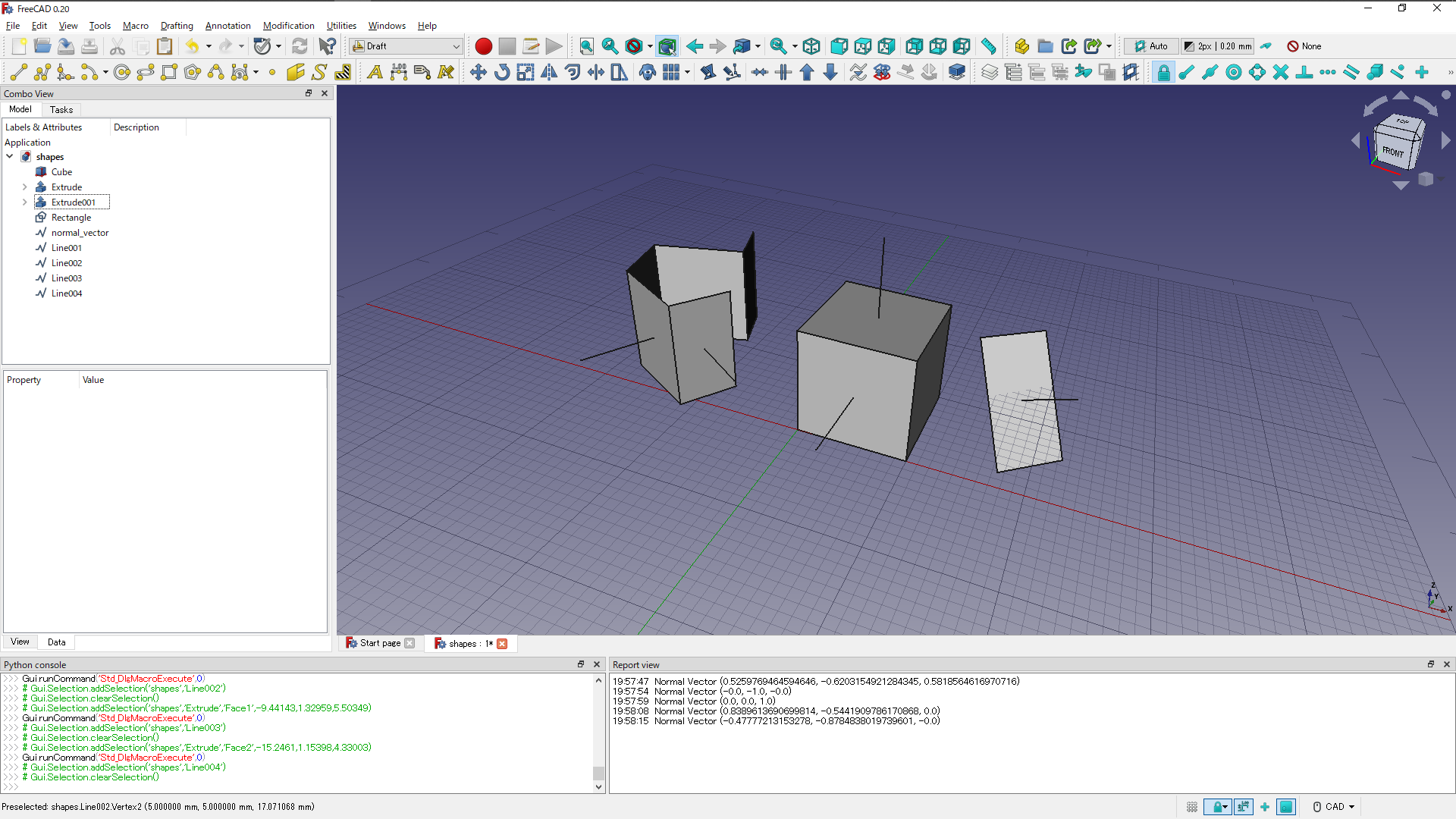
Normal Vector 法線ベクトル(X, Y, Z)(mm)
【使い方】
・対象となる面を選択した状態で本スクリプトを実行してください
・何も選択していない状態で実行するとWarningが表示されます
・正常に実行されればReport viewに法線ベクトル成分が出力されます
・モデルビューに法線ベクトルを表す線分が描画されます
FreeCADで具体的な面に適用した例を示します