今回はFreeCADで断面性能を表示させるPythonスクリプトを説明します
AutoCADにはリージョンの断面性能を表示させるマスプロパティ(MASSPROP)というコマンドがあります
複雑な断面形状の図心位置や断面2次モーメント等を知りたいとき大変重宝する機能ですね
これと同じ様なことをFreeCADでもやりたいというお話です(*´ω`*)
前提条件として
FreeCAD上で定義された単一の面(Face)を対象とします
XY平面,XZ平面, YZ平面のいずれかに平行に配置されていることを想定しています
FreeCADのv0.20でしか動作検証してません
Pythonスクリプトを以下に示します
【props_of_section.py】
import Draft
def norm(a, b, c=0):
""" Return norm of argument numbers """
return (a**2 + b**2 + c**2)**(1/2)
def section_modulus(shape):
""" Calculate Section modulus from argument shape """
BBx = shape.BoundBox
CoM = shape.CenterOfMass
x1 = abs(BBx.XMax - CoM.x)
x2 = abs(BBx.XMin - CoM.x)
y1 = abs(BBx.YMax - CoM.y)
y2 = abs(BBx.YMin - CoM.y)
z1 = abs(BBx.ZMax - CoM.z)
z2 = abs(BBx.ZMin - CoM.z)
MoI = shape.MatrixOfInertia
Ixx = MoI.A11
Iyy = MoI.A22
Izz = MoI.A33
Z1 = FreeCAD.Vector(Ixx/norm(y1, z1), Iyy/norm(x1, z1), Izz/norm(x1, y1))
Z2 = FreeCAD.Vector(Ixx/norm(y2, z2), Iyy/norm(x2, z2), Izz/norm(x2, y2))
return Z1, Z2
def plot_point(vector_a):
""" Plot point from argument vector """
point = Draft.make_point(vector_a)
Draft.autogroup(point)
def plot_line(vector_a, vector_b):
""" Plot line from argument vectors """
line = Draft.make_line(vector_a, vector_b)
Draft.autogroup(line)
def plot_principal_axes(shape):
""" Plot principal axes from argument shape """
BBx = shape.BoundBox
CoM = shape.CenterOfMass
length_axis = norm(BBx.XMax-CoM.x, BBx.YMax-CoM.y, BBx.ZMax-CoM.z)
I_eivect1 = shp.PrincipalProperties.pop("FirstAxisOfInertia")
I_eivect2 = shp.PrincipalProperties.pop("SecondAxisOfInertia")
I_eivect3 = shp.PrincipalProperties.pop("ThirdAxisOfInertia")
plot_line(CoM, CoM + length_axis*I_eivect1)
plot_line(CoM, CoM + length_axis*I_eivect2)
plot_line(CoM, CoM + length_axis*I_eivect3)
obj = FreeCADGui.Selection.getSelection()
if len(obj):
shp = obj[0].Shape
FreeCAD.Console.PrintMessage("-------- Properties of Section --------\n")
FreeCAD.Console.PrintMessage("Area = %f\n" % shp.Area)
FreeCAD.Console.PrintMessage("Length = %f\n" % shp.Length)
BBx = shp.BoundBox
FreeCAD.Console.PrintMessage("Boundary box = (%f, %f, %f, %f, %f, %f)\n" % \
(BBx.XMin, BBx.XMax, BBx.YMin, BBx.YMax, BBx.ZMin, BBx.ZMax))
CoM = shp.CenterOfMass
FreeCAD.Console.PrintMessage("Center of mass = (%f, %f, %f)\n" % (CoM.x, CoM.y, CoM.z))
MoI = shp.MatrixOfInertia
FreeCAD.Console.PrintMessage("Second moment of area = (%f, %f, %f)\n" % (MoI.A11, MoI.A22, MoI.A33))
FreeCAD.Console.PrintMessage("Product of inertia = (%f, %f, %f)\n" % (MoI.A12, MoI.A13, MoI.A23))
Rg = shp.PrincipalProperties.pop("RadiusOfGyration")
FreeCAD.Console.PrintMessage("Radius of gyration = {}\n".format(Rg))
I_eivals = shp.PrincipalProperties.pop("Moments")
FreeCAD.Console.PrintMessage("Principal moments of inertia = {}\n".format(I_eivals))
plot_point(CoM)
FreeCAD.ActiveDocument.Point.Label = "center_of_mass"
plot_principal_axes(shp)
FreeCAD.ActiveDocument.Line.Label = "principal_axis_1"
FreeCAD.ActiveDocument.Line001.Label = "principal_axis_2"
FreeCAD.ActiveDocument.Line002.Label = "principal_axis_3"
FreeCAD.ActiveDocument.recompute()
Z1, Z2 = section_modulus(shp)
FreeCAD.Console.PrintMessage("Section modulus = (%f, %f, %f, %f, %f, %f)\n" % \
(Z1.x, Z2.x, Z1.y, Z2.y, Z1.z, Z2.z))
else:
FreeCAD.Console.PrintMessage("-------- No valid setected object! --------\n")
※主軸ベクトル(I_eivect1~3)を表示させる箇所はコメントアウトしてます
【表示項目一覧】
Area				断面積(mm2)
Length				周長(mm)
Boundary box			境界枠(X1, X2, Y1, Y2, Z1, Z2)(mm)
Center of mass			図心(X, Y, Z)(mm)
Second moment of area		断面2次モーメント(Ixx, Iyy, Izz)(mm4)
Product of inertia		慣性乗積(Ixy, Ixz, Iyz)(mm4)
Radius of gyration		回転半径(R1, R2, R3)(mm)
Principal moments of inertia	主慣性モーメント(I1, I2, I3)(mm4)
Section modulus			断面係数(Zx1, Zx2, Zy1, Zy2, Zz1, Zz2)(mm3)
※断面2次モーメントは図心を通り座標系に平行な各軸回りの値となります
(AutoCADのMASSPROPではワールド座標系の各軸回りの値となっており,挙動が異なるので注意してください)
【使い方】
・対象となるフェースを選択した状態で本スクリプトを実行してください
・何も選択していない状態で実行するとWarningが表示されます
・正常に実行されればReport viewに断面性能が出力されます
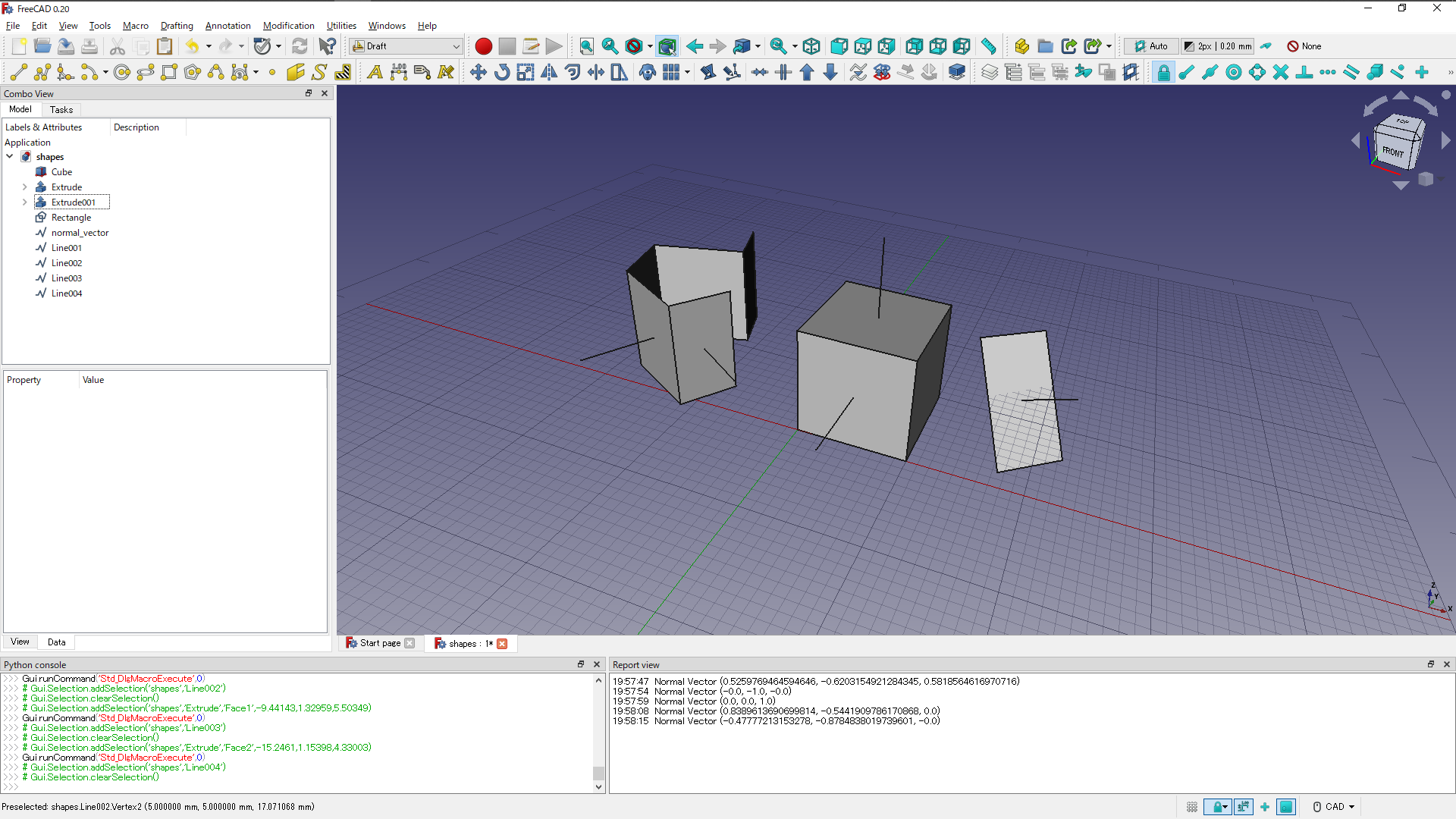
・モデルビューに図心を表す点と主軸ベクトルを表す線分が描画されます
FreeCADで具体的な断面に適用した例を2つ示します
矩形断面(50x100)

不等辺山形断面(L200x90x8/14)